Apollo3 Patient Isolation Hood
Overview
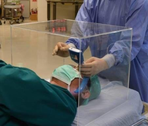
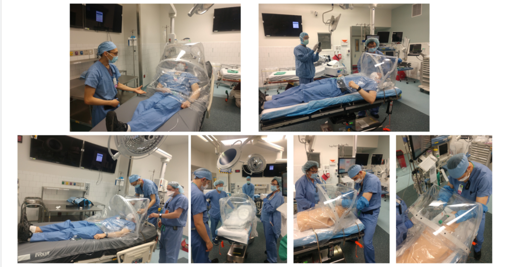
The Apollo Patient Isolation Hood (PIH) is a localized negative-pressure ventilation system for hospital beds to help contain the droplet spread of COVID-19, including during aerosol-generating medical procedures such as intubation and extubation. The PIH encloses a patient’s upper torso and head in a negative-pressure environment. It provides barrier protection between a healthcare provider (HCP) and patient, and aerosol control via the negative pressure environment. The hood may also contain the spread of the virus from less critically- ill patients, reducing the need for invasive procedures.
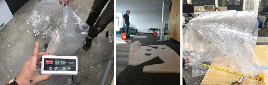
The versatility of the Apollo PIH means that it can be used in any care setting (OR, PACU, ICU, ED, EMS) and can be rapidly secured to a variety of beds. The lightweight (<5 lbs) design allows for ease of assembly, use, and disposal. The primary structure is composed of a single flat sheet of PETG plastic that is assembled into a 3-dimensional form, minimizing the number of seams for optimal viewing clarity. Flexible sealed arm ports provide HCP access to patients. A minimal amount of folds and seams in the primary enclosure provide optimal viewing clarity.
Precedents
Dana Box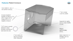
Limitations:
- Too rigid, made of multiple parts, limited arm flexibility,non- integrated glove detail, not easy to manufacture, heavy, not easy to transport, 200-300$ range.
J.P Hood
Limitations:
- Reduced optical clarity, pressure pulls thin plastic.
Apollo3
Concept
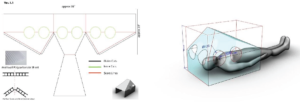
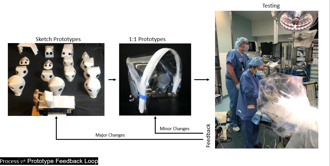
The main intention was to use simple techniques of creating stable 3d forms from readily available flat sheets and minimal joinery, which can be rapidly deployed to help frontline medical workers. The design of the ‘Apollo’ is based on the principles of ‘Active Bending,’ which describes surfaces that base their geometry on the elastic deformation of initially straight elements((Gengnagel, Alpermann, and Hernández 2014)).
Material
All initial small-scale prototypes were made of 130 gsm (80lb) Bristol paper with a Cricut Maker, which proved to be a quick and straightforward method for a rapid iterative process.
PETG, well known as a material for scaling up origami concepts (Baerlecken et al. 2014), was used to make prototypes at full scale. Both 30mil (1/32”) and 60mil (1/16”) PETG sheets work well based on the required size and stability that is needed for the PIH. Most of the prototyping was done with 60 mils and the final design is a combination of stability, flexibility, and lightness.
Design
The initial guidelines of the design were flat foldability, optical clarity, and simple assembly. The origami approach catered to most of this requirement, but the designs still had seams at the folds.
Hence the next step in the design process was to achieve bending without folding, and thus we looked at the principle of ‘Active Bending’.
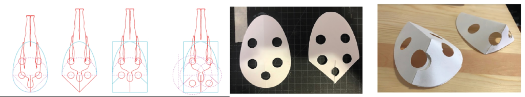
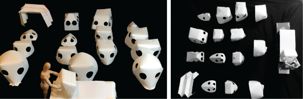
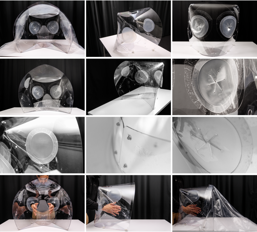
Applying spherical linkages enabled us to get rid of the folds and have a seamless 3d form from flat sheets. Small single vertex spherical prototypes were made to test the stability of the structure. This concept was then applied to a simple unfolded cuboid based on the clinical dimensions with partial overlap between the sides. Modifications were made to improve the interface of the base perimeter with the bed and to taper the viewing angle.
The design went through numerous iterations based on the anthropometric, functional, and clinical requirements associated with the process of intubation and provided by the clinicians at MGB & BCH. The design needed to cater to a lot of different parameters and be adaptable so that it could be used in various hospital settings, attached to different sized hospital beds and be used on patients of varying age groups and body type. A variety of alternative designs were prototyped, which differed in size, attachment details (rivets, slots/tabs), and ability to nest on commonly available sheet stock as well as available fabrication infrastructure.
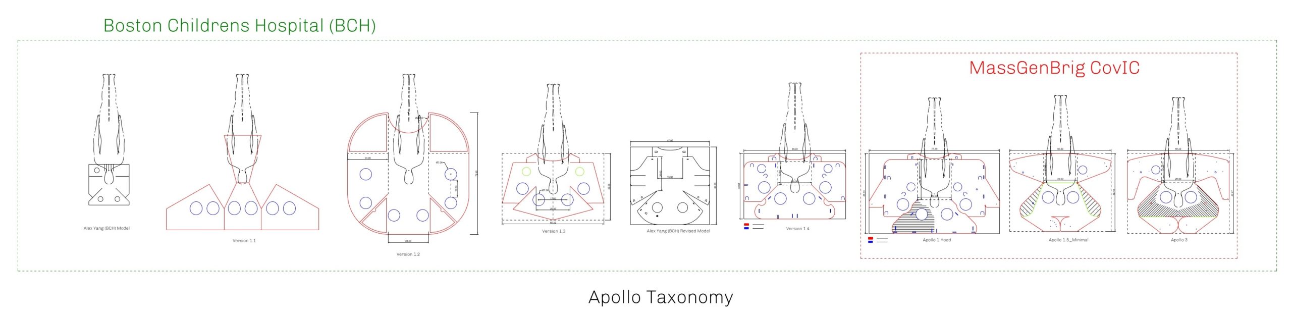
Some of the prominent iterations are briefly explained below.
Apollo3
The novelty of the ‘Apollo3’ design is that it can be made up of thin sheets of flat materials, and based on the calculated overlap of the side-arms, a double thickness structure is provided at the base for stability while making the rest, pliable and light.
Key Features
Several key features of the prototype are outlined below:
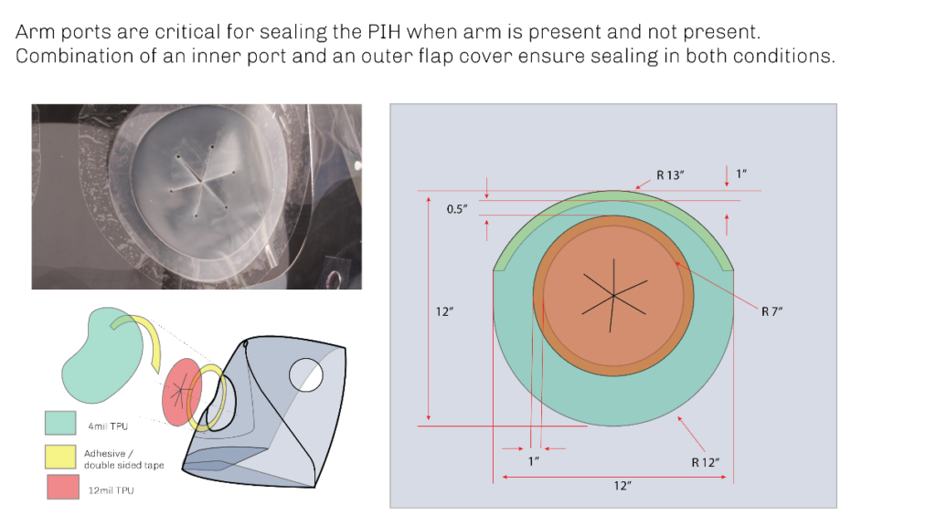
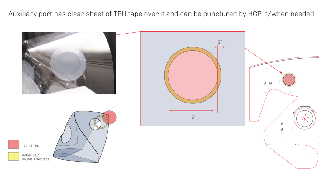
- (2) arm ports at the rear of the PIH provide healthcare provider (HCP) access to the patient. – An additional auxiliary port on one side of the PIH allows for further patient access as needed.
- Minimal surface seams allow for an unobstructed view of the patient.
- Adaptable attachment mechanism allows for use on a variety of bed types (OR, ICU, etc.)
- Side arms provide a double thickness at the base of the PIH for stability and structure
- Various suction ports accept standard negative pressure hoses, including a ⅞” diameter (typical in OR) as well as smaller 3/16” ID tubing (standard in the ICU).
Fabrication
The fabrication of the ‘Apollo3’ hood can be subdivided into two parts:
- The enclosure
- The functional elements
For the Bill of Materials. See ‘here.’(Link)
Enclosure
The primary design element of the Apollo PIH is the enclosure – a thin sheet of clear PET-G plastic in 60mil (approximately 1/16”) thickness. It can be CNC cut from a flat sheet of PET-G measuring a minimum of 48” x 72”. The Apollo PIH enclosure measures approximately 22” in width, 23” in height and 22” in depth and is about 0.15 m3 in volume.
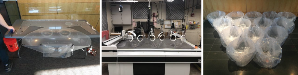
The Apollo PIH requires a minimum stock size of 72” x 48”. The stock can be cut using several CNC processes, including a knife cutter, laser cutter, or router. In the case of a CNC router, a ⅛” diameter endmill is required to cut small interior features successfully. A list of suggested cut settings is provided below. Please keep in mind that these settings are specific to the machines listed and will likely need to be modified for other scenarios.
Knife Cutter (Zund G3M2500)
Bed Size: 98” x 52”.
Tool: Universal Cutting Tool (UCT) with glide shoe)
Blade: Type6 blade
Depth: 0.02” per pass
Speed: 6” per second
Total Time: ~ 18 minutes.
Laser Cutter (450 Watt Multicam Magnus 48×96 CNC Laser, 4” Focal Lens)
Speed: 480 IPM
Power 60%
Frequency: 10,000 PPI
Base Plate Braking/Bending
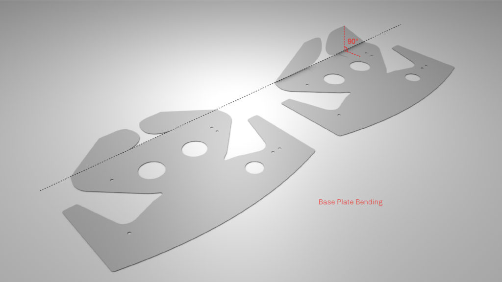
The base plate (2 offshoots located at the base of the design) is responsible for imparting stability to the hood, and also the method of connection makes it adapt to different bed sizes as it makes the hood behave as a compliant mechanism.
The base plate portion of the Apollo PIH enclosure must be cold-formed to a 90-degree angle relative to the rest before assembly. To date, this has been successfully accomplished on a sheet metal finger brake, such as the Baileigh SBR-4020 shear brake roll (Link). Additional forming processes, such as the use of a line brake or heat gun or design modifications to the enclosure, such as eliminating the base plate or incorporating a secondary hinge mechanism, exist as potential alternatives. However, they have not been tested by the design team.
Snaps / Connectors
A variety of different snaps/connection options were explored, ranging from pop-rivets, push-in rivets, tabs/slots, and button snaps to keep the actively bent shape stable.
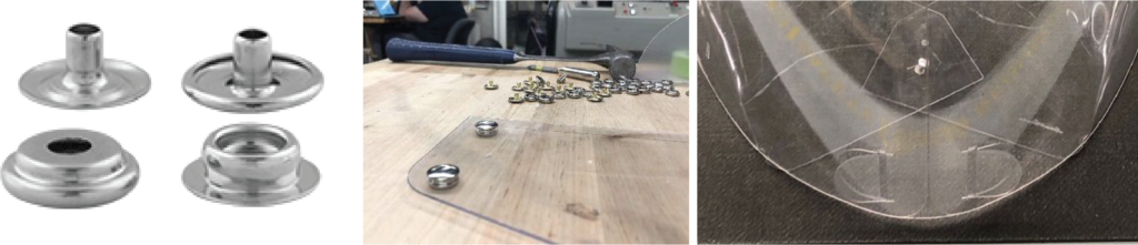
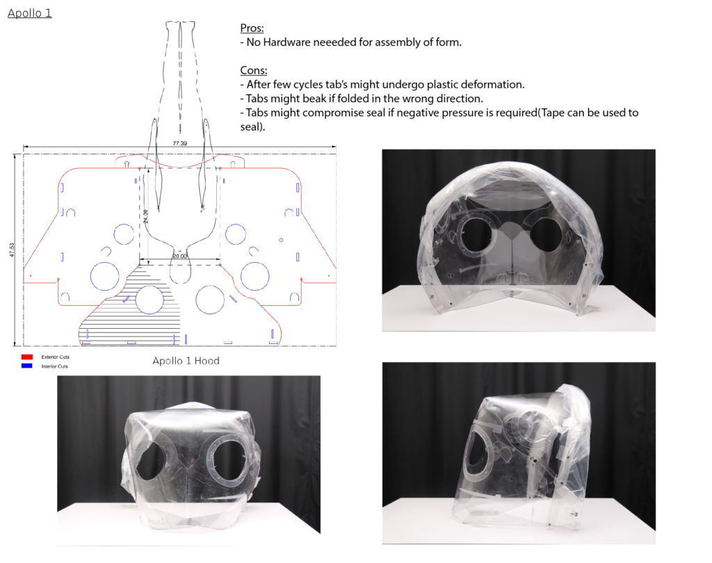
The fabric snaps added an extra step in the assembly by creating an offset in thickness between the overlapping sheets. They compromised the airtightness of the hood and increased the risk of contamination. The tabs/slots proved advantageous by not needing extra hardware, hence making the hood recyclable due to the presence of a single material but were susceptible to plastic deformation and breaking after multiple cycles.
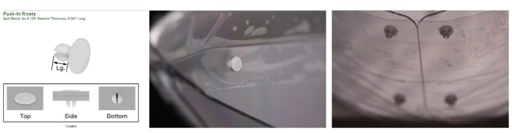
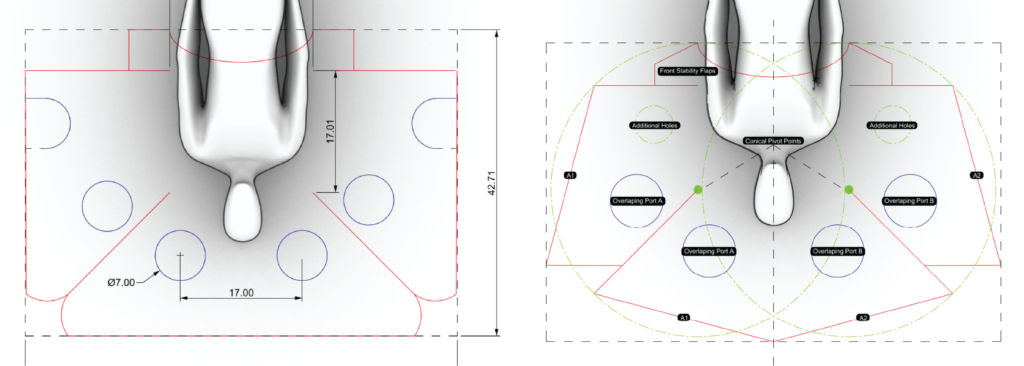
Push-in Plastic rivets were selected as the preferred fastener, as they were simple to use and had no sharp edges that could catch on to clothing, medical instruments, etc. 3/16” holes in the main enclosure facilitated the riveting and were done by hand. Sixteen rivets are needed (8 per side of symmetry) for maintaining the shape of the Apollo while two rivets (or one rivet & a button snap)are necessary for the baseplate ( 1 to pivot (red) and 1 to lock (blue)).
The width of the Apollo can be adjusted by adjusting the location of the pivot and the lock. A simple grasshopper script was used to determine the position of the snaps so that it gives a required width (in case of the ‘Apollo 3’, it was 23inches). Multiple perforations can be added to have it adapt to a range of widths.
Functional Add-ons
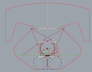
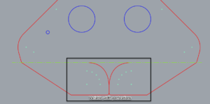
ArmPorts + Auxiliary Ports
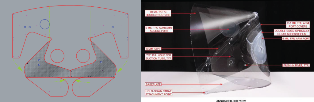
Each arm and auxiliary port on the Apollo PIH is composed of three primary components – a laser-cut five mil TPU portal, a transparent, double-sided adhesive film, and a port cover.
- TPU Portal: Laser cut from 5 mils TPU. The portal is an inverted “Mercedes” design, with circular relief holes at the tip of each cut to minimize the potential for tearing. It can be CNC cut on a laser cutter or a knife cutting machine such as a ZUND.
- Adhesive Ring: The adhesive ring can be cut from a sheet of the adhesive film.
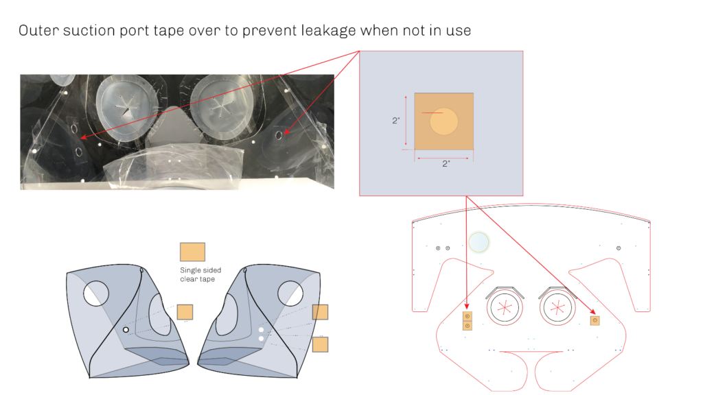
- The port cover/flap
Alternatives
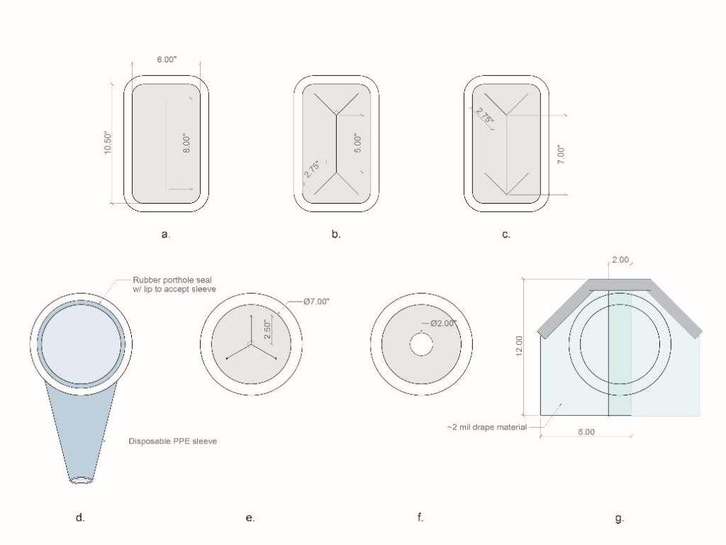
Multiple iterations of the arm port design were undertaken with various materials and can be found in the diagram above.
- Versions a and f Require a thinner gauge or extensible material as they can otherwise restrict arm movements while in use. Version f also requires a secondary drape taped over the opening to maintain a seal
- Versions b, c, and e work well with the specified 5+mil TPU and 1/16” silicone sheets (available on McMaster Carr). They feature a self-closing design and, when used with the silicone sheets, may not require a covering drape. Version c is best for thinner materials that lack the stiffness to hold their shape overwise
- Version d makes use of disposable PPE sleeves widely available in many material types. The sleeve is stretched around a rubber porthole seal (such as [this product).
- Version g simply uses two pieces of the drape material with an overlap to help limit air escape when in use.
- Transparent PVC sheets were experimented with in both 0.08” and 0.04” thicknesses but were found to be too stiff and often grabbed at the sleeves and gloves when in use.
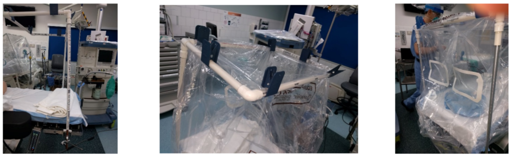
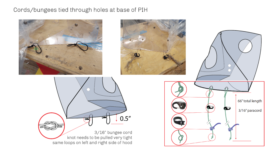
Bed Attachment Detail
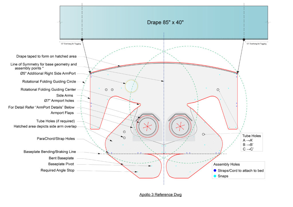
Perforations are located on the base perimeter (dark blue in Reference drawing) of the backplate to enable the use of cords/straps to attach the Apollo to different sized beds.
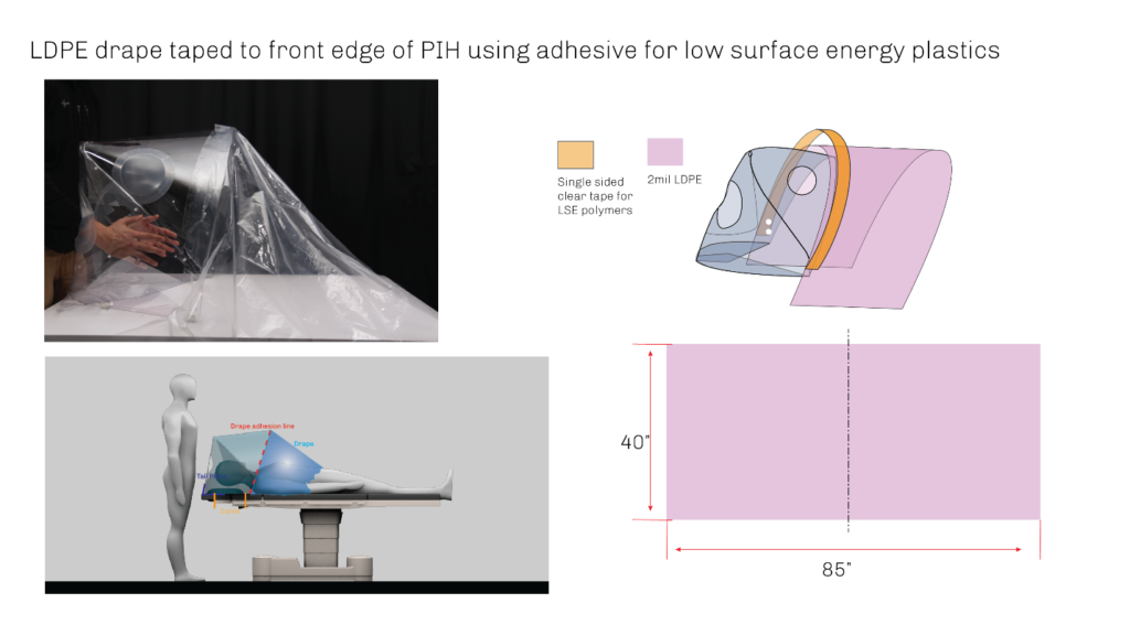
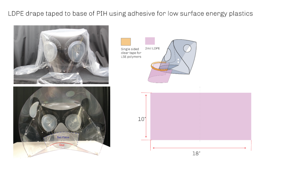
Drape
The drape is a rectangular piece of LDPE with dimensions 85” x 40”. Refer to the reference drawing and assembly instructions for details. A 12” offset has been left on both ends to facilitate tucking under the patient to get a good seal.
Tail Piece
Assembly
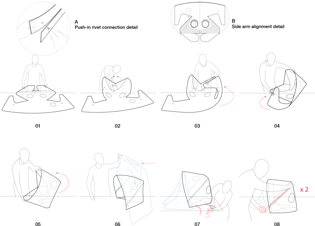
- Step 01: Place Apollo PIH enclosure on a flat surface with the folded baseplate facing upwards.
- Step 02: Fasten the opposing sides of the baseplate together using two push-in rivets located on the baseplate. See detail A for connection detail.
- Step 03: Fold one side-arm toward the interior of the enclosure. Fasten to the central portion of the enclosure using (8) push-in rivets.
- Step 04: Repeat Step 03 for the opposite side-arm.
- Step 05: Place the Apollo PIH upright so that the baseplate is resting on a horizontal surface.
- Step 06: Attach the plastic drape to the front edge of the Apollo PIH using double-sided tape.
- Step 07: Fasten the provided straps to one side of the Apollo PIH.
- Step 08: Adhere clear tape over the external seams of the Apollo PIH (one per side), taking care to cover the seam completely.
Function
Storage and Stacking
Negative Pressure Application-MGH
- PlaceHolder- Graph from MGH
- Instructions to connect vacuum (Link)
Documentation
Hood
MGH Clinic Tests
Acknowledgments
- Several clinicians provided key clinical feedback that drove design decisions, from MGH Anesthesia: Samuel Smith, MD, MPH; JP Wang, MD, PhD; Michelle Szabo, MD; Scott Streckenbach, MD; Alex Kuo, MD; Kendrick Shaw, MD, PhD; Angela Dai; Matt Vanneman, MD; Celeste Day. From MGH Pediatrics, Kris Olson. From the MGB Center for COVID Innovation; Li Li, PhD; Aditya Kumar; and Gary Tearney, MD, PHD.
- Chris Hansen, Digital Fabrication Technical Specialist at the Harvard GSD; Eric Howeler, Associate Professor of Architecture at the GSD; Saurabh Mhatre, Research Associate at the Harvard GSD & Harvard CGBC; and Nathan Phipps, played key roles in refining, prototyping, and coordinating fabrication of the Apollo 3 design. Zach Seibold, Jonathan Grinham, Daniel Tish, Daniel Castello and Ryan Pierce participated in design iteration and early prototyping.
- James Weaver, Senior Research Scientist at the Wyss, facilitated the initial collaboration and has been instrumental in sourcing materials.
- The Boston Children’s Hospital Surgical Innovation Fellowship team, including Heung Bae Kim, MD; Farokh Demehri, MD; Robert Crum, MD; Kyle Wu, MD; Brianna Slatnick, MD; and Alex Yang, BS, helped to develop the first versions of the Apollo design and provided clinical input throughout the design process.
- Initial design prototypes were produced with the help of PolyFab, and Roger Diebold (CEO, Solchroma Technologies) along with H. Loeb Corporation.
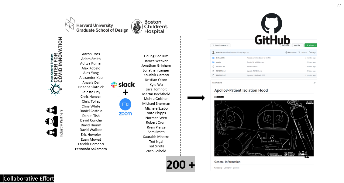
A full attribution list is as follows Aaron Ross, Adam Smith, Aditya Kumar, Alex Kobald, Alex Yang, Alexander Kuo, Angela Dai, Brianna Slatnick, Celeste Day, Chris Hansen, Chris White, Daniel Castelo, Daniel Tish, David Concha, David Hamm, David Wallace, Eric Howeler, Euan Mowat, Farokh Demehri, Fernanda Sakamoto, Heung Bae Kim, James Weaver, Jonathan Grinham, Jonathan Langer, Koushik Garapti, Kristian Olson, Kyle Wu, Lara Tomholt, Martin Bechthold, Mehra Golshan, Michael Sherman, Michele Szabo, Norman Wen, Robert Crum, Ryan Pierce, Sam Smith, Saurabh Mhatre, Ted Ngai, Ted Sirota, Zach Seibold.
References
Baerlecken, Daniel, Russell Gentry, Matthew Swarts, and Nixon Wonoto. 2014. “Structural, Deployable Folds-Design and Simulation of Biological Inspired Folded Structures.” International Journal of Architectural Computing 12 (3): 243–62. https://doi.org/10.1260/1478-0771.12.3.243.
Gengnagel, Christoph, Holger Alpermann, and Elisa Hernández. 2014. Active Bending in Hybrid Structures.